Have you already decided to adopt this revolutionary technology?
You have decided to make the switch to this revolutionary technology, following in the footsteps of many manufacturers who have already been won over by BIM including Parker Transair, Skydome, and Hitachi. We can only congratulate you on your decision.
The shift to BIM requires several stages, and, in particular, modelling of your products in BIM format. Two distinct phases are required: modelling the geometry of your products and enriching the data of your 3D objects to transform them into genuinely high-quality BIM objects.
This article focuses on the geometric modelling phase. This is an important phase and requires an element of caution because, if it is defined or executed poorly, it can be expensive. On the other hand, if you are properly prepared, it will enable you to save a great deal of time and, consequently, money. Here, therefore, are our eight tips for successful modelling.
1) Above all, ask the most fundamental question: why do I want to create a model of this product? By answering this question, you will enable your modelling consultant or internal designer to understand your needs. This is why, at the kick-off meeting, you should set out your needs and expectations as clearly as possible. Anything that is not clear in your mind will not magically become clear for your consultant or designer. It is therefore worthwhile to create an accurate, exhaustive quote or breakdown of the task at hand: which product needs to be modelled? Do different product variations (in colour or material, etc.) need to be taken into consideration? Do you need to model a door handle? Explain precisely what your BIM objects will be used for, and by whom: architects, thermal engineers, general businesses, economists, etc.? With a sound understanding of your BIM products and their uses, you will avoid modelling some details that will never be used while overlooking others that are essential.
For example, a major French manufacturer that specialises in acoustic systems wanted to model its false ceilings. The company had initial models created, and only after this initial engagement was the manufacturer able to refine its original requirement to define the value of the objects it wished to offer to its users. The manufacturer saw it as essential to be able to create an estimate of the number of ceiling tiles required, based on the layout of the building. This meant that lighting and heating elements had to be taken into account when designing the false ceiling.
2) Providing as much information as possible to understand the geometry of the object will help to ensure that a project is a success. No one knows your products better than you do, which means that your help is therefore valuable. Don’t hesitate to provide as much information as possible to your consultant. This means dimensions and references that are specific to the modelling process. A well-defined product catalogue makes it easier to read the information and, by default, will ensure that the modelling is organised more effectively. It is, therefore, essential that you share up-to-date technical files. Moreover, an existing CAD model, such as a .dwg (AutoCAD), .SAT, .STEP or .DXF file, can be a significant help.
Retrieving details from the CAD system can help improve the accuracy of the geometry and will ensure significant time savings for your consultant. BIM modelling is not about converting a .dwg file to .rvt and, indeed, this process often results in excessively large and complex models. Nevertheless, supplying CAD files to modellers helps them to understand your products.
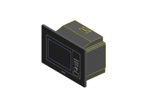
Example of a CAD file (AutoCAD in this case) imported into Revit:
Imported .dwg file:

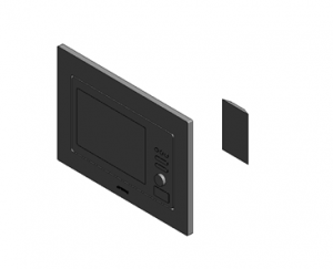
Loss of 3D data as soon as the file is modified:

The team is forced to remodel the product, with the final result:

Finally, if a Revit format model is required even though there is an existing CAD file, the process can sometimes halve the file size. This is a crucial issue, which we will address in detail at paragraph 6 of this article.
3) Work hand in hand together. A “happy partnership” between the manufacturer and the consultant means moving forward together. Be a stakeholder in the modelling process. Communication and discussions between the various stakeholders is undoubtedly one of the keys to a healthy working relationship. Never hesitate to raise any questions you may have. Following the work closely will help you to identify any adjustments that may become necessary in a timely fashion. By identifying these issues as early as possible, you enable the modelling team to avoid repeating any mistakes and will save time that is valuable to say the least.
To achieve this, BIM&CO provides a private group for manufacturers, where an object is deposited once it has been modelled. It is very easy to access and it provides an overview of the progress of the work. It also includes a discussion space, where the various stakeholders can engage in dialogue. Finally, it is also an effective tool for the first object in a range to be checked and approved before moving on to the modelling of the entire range.
4) Perfect familiarity with the modelling software. It might appear obvious, but there is no point in having high-quality tools if you don’t know how to use them properly. The more skilled you are at using the software, the greater your ability to avoid or overcome a problem if necessary. ArchiCAD modelling does not require the same skill set as Revit modelling. Indeed, the interface for managing references is extremely different from the one used in ArchiCAD.
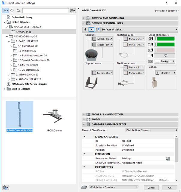
In ArchiCAD, the user has more freedom to represent product options on an ad hoc basis, and can organise the various configuration stages one after another. Everything is organised around the .gdl format, which is a code language that allows geometry to be created and parameters to be associated with the user interface. The end result: a script with lines of code, leading to a geometric form and an interface to manage it.
ArchiCAD interface:


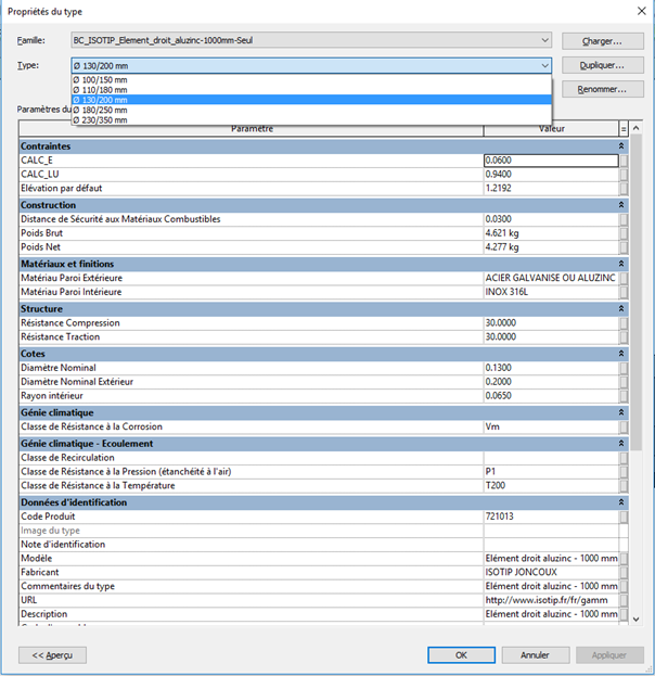
In Revit, the user interface and the management of properties both follow a set format.
The geometric form is shaped using extrusions, directly from the user interface, linking distances with settings that provide the user with information. Revit also covers all parts of the building, from its structure through to its piping, coatings and its mechanical, engineering and plumbing aspects.
Revit interface:
Each software package therefore offers its own benefits: it is up to you to decide which is more appropriate to the specific needs of the users of your BIM objects.
5) Do you need a configurable object? Does the product that you want to model feature variable dimensions or colours? Does your product contain several line items? If so, you will need to model your product as a family to make it possible to include all its different variants and line items. This means that the product is configurable: the user can vary any of the data provided at the level of the family to suit the needs of a particular project.
If we take the example of a window: a window is a product with a format that is rarely standard because the dimensions are generally defined on a case-by-case basis. The product must, therefore, be modelled as a configurable object to ensure that it can be used in a digital template. On the other hand, if we take the example of a mixer tap – which is a standard product with characteristics that never vary – it does not need to be modelled as a configurable object.
6) Understand how the size of the object model matters. It is essential to bear in mind that each geometric detail counts. You must appreciate that the product will not be depicted as it would appear in reality. As such, some things will inevitably require simplification. Indeed, the size of a standard Revit family is already quite large yet, when laying out a building, it is important to ensure that a BIM object can be moved around smoothly and quickly. Most BIM objects that are in use are smaller than 500 kB in size. As such, BIM&CO prefers objects to be modelled in LOD 200 and LOD 400. The first format will only contain very few details, but it takes up less space and still contains all necessary data. This, therefore, makes it much easier to work. The second option genuinely assists the work performed by the business: with a great deal of detail, it can be used to create a layout plan and will form a guide to be followed at the site. If the file size is too great, however, the object will not be suitable for use in performance modelling. By offering LOD 200 and LOD 400 BIM objects, we are able to meet the demands of the pre-project stage as well as the delivery phase during the project. BIM&CO technology makes it possible to manage several LODs for a single object. Users can therefore update the object as and when required as the project progresses.
A door modelled at LOD 200 level will only represent a simple, cubic geometric shape that is free from detial. On the other hand, at LOD 400 and when viewed from above, the object will contain the profile of the frame, the inset panel, and will show the impact of the lintel and the casing for the roller shutter. When viewed from the front, the LOD 400 will also include the embedded nested family (allowing sub-categories within the generic metric model and for materials to be added), as well as the opening within the nested family (meaning that the material can be associated with a specific parameter).
7) Connectors are essential elements and should not be taken lightly. They are primarily useful in the HVAC and MEP domains and allow the direction of flow to be shown in a BIM object: for example, a mixer tap contains three connectors – a hot water inlet, a cold water inlet, and an outlet. Their use also makes it possible to distinguish between an MEP component and an architectural or structural component. Their primary value comes from their ability to define the continuity of elements within a network and the way that the elements behave in respect of each other. Poorly configuration of your connectors will prevent the BIM object from being used correctly, leading to a failure in the associated network. Even worse, a component that lacks connectors cannot form part of a system typology.
If a connector is added to an object family, this should be a conscious decision so that it can form part of a purpose-designed system under all circumstances. It is highly recommended that you use a construction plan to position it, because this is the only way to control the position of a connector with complete accuracy, because it could otherwise move around following the family-level parameters (such as width, height, depth, and angle).
Naturally, the specified dimensions (width, height, diameter) and orientation are decisive factors in the way that connections are made with compatible components. Therefore, it is important to ensure that adequate connectors are integrated within each family, where appropriate – but you must also ensure that they are configured correctly, with the right choice of discipline, calculation methods, system type, and actual parameter values (flow direction, number of poles, geometric sides, etc.).
8) Never overlook anything: orientation, 2D icons, etc.
To ensure that an object can be used simply and quickly, each geometric model must be able to refer to a shared system of coordinates relative to its geographic position. Similarly, 2D is still widely used and incorporating a 2D symbol that pertains to your object can only help matters.
How involved should I be in the project? What role do connectors and file sizes play? Does my object need to be configurable? As a manufacturer, it is essential to ask yourself the right questions at the right time.
Professional support and the use of technology to offer a genuine management solution for your objects will help you to answer the most important question – which is to understand how you wish your BIM objects to be used!
